Meccano Model Images
The images on this page are a subjective collection of images of various Meccano \ Erector models that I like.
Images supplied by Geoff Brown.
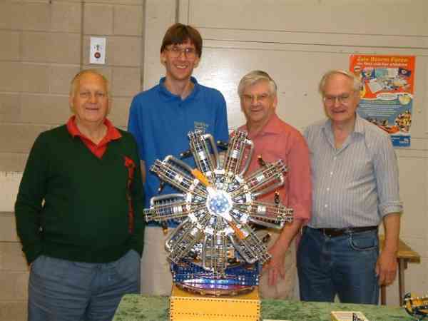
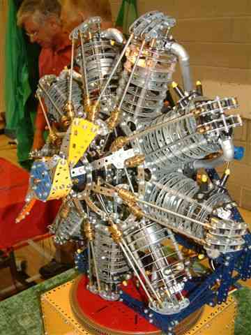
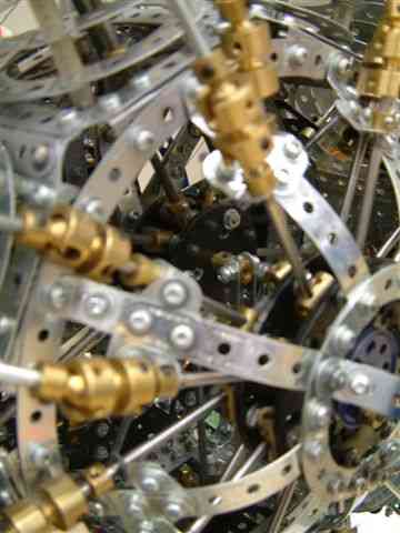
Bentley BR2 Rotary Aeroplane engine. Built by Russell Carr of Wakefield. An original design at a little over half size. Features twin spark plugs. Dummy magnetos running at correct speed switch the spark. Carburetor with moving throttle slide and jet. Correctly operating valve gear. 288 curved strips were used in constructing the cylinders.
Above: Russ Carr's Bentley engine plus Geoff Wilson, Russ himself, Pete Pyefinch and Peter Gurd. Russ, the builder is the tall handsome one! This image is important because from a distance, you can see exactly how the pistons move up and down the bores as the bores rotate round the fixed crank.
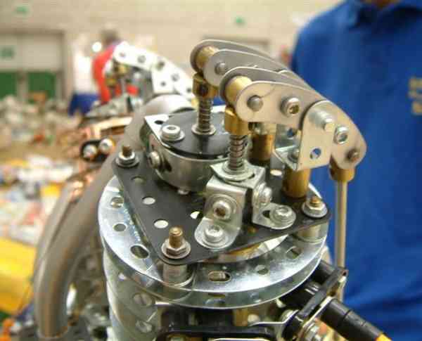
Cylinder head detail. Finding enough Mechanised Army bushwheels was a problem...
Above: View showing carburetor at rear. The model is wrong about ignition contact . There are two spring loaded buffers - one cabled to each magneto.
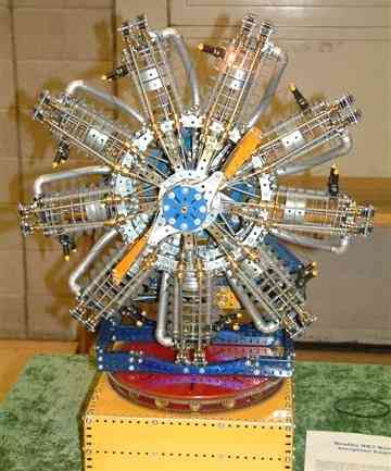
Above: Engine Full On front view.
Above: Side view showing position of valve cams behind prop hub.
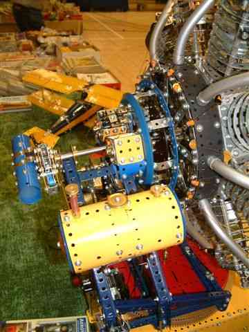
Above: Side view at back, showing 3/8" dia main support
rod, 2 x 1.1/2" square 'magnetos'and oil tank in foreground. Between the
6" pulley halves and the
7.1/2" circular strip is a circular spark distributor plate with a spring
loaded buffer bearing on each of nine contacts in turn. The magnetos driven at
half speed (I think) give one spark per two revs for the 4-stroke cycle.
HT cables are bare copper wires taken through plastic ferrules (ex space base
kit etc) to the spark plugs, two per pot.
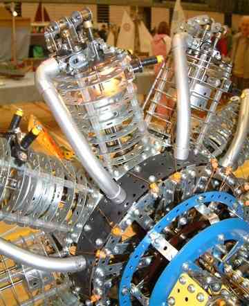
Above: Another view showing cylinder and inlet tract detail. Inlet manifolds are standard U.K. copper tubing and fittings. Nice neat fit into a chimney adaptor. Elbows at top end slip over small tyres from latest kits.
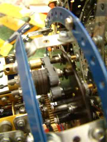
Above: Close up of the rotating distributor plate and the buffer contacts.
Above: Focus on 'crankpin', plumb centre with special 'wristplate'.
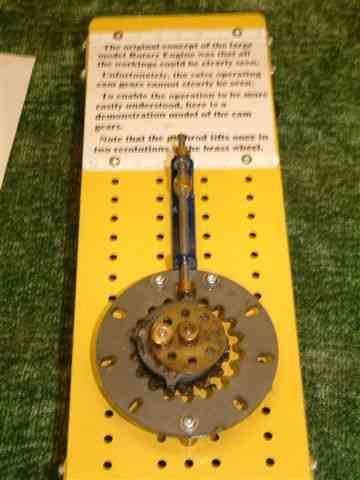
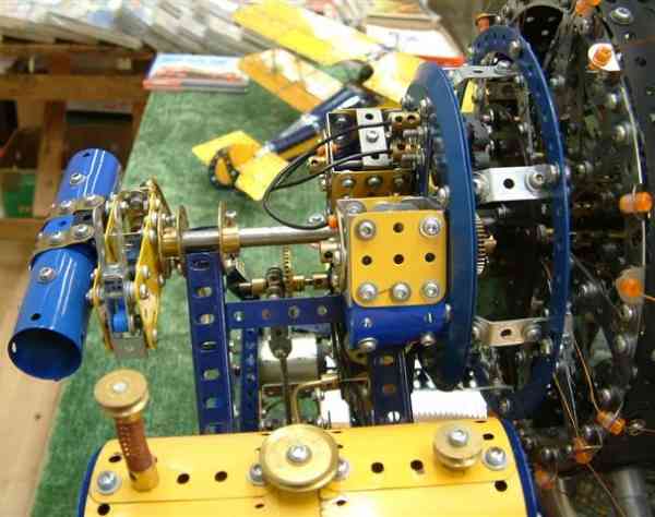
Above: A demonstration model of the cam gear drive.
~
Russell wrote as a caption: The building of this engine was
inspired by visits (while exhibiting with the SMG) to the Northern Model
Engineering exhibition and the working engines by model engineers. I
wished to know the internal arrangement of these engines. I could
not see the arrangement of the nine connecting rods onto one crankpin, or how
the valve gear operated. I did not understand the "timing" of
the engine movements.
I decided it would be an interesting subject to interpret in Meccano, in a
skeletal form to show as much of the internal workings as possible. It was
challenging to model because there is no "base plate" to the engine
and the division of nine cylinders is not a Meccano friendly one.
The piston stroke can be clearly seen; also the spark. The valve timing
demands closer study due to the smaller movements but it does work correctly.
I acquired the book by L K Blackmore and despite close study it wasn't until the
various mechanisms were constructed that I began to understand the operation.