Meccano Model Images
The images on this page are a subjective collection of images of various Meccano \ Erector models that I like.

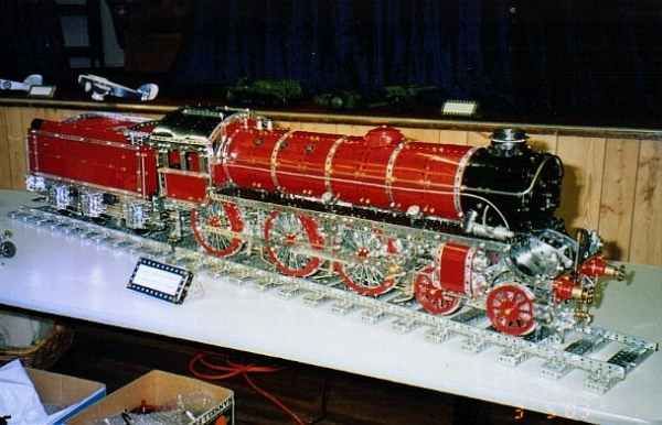
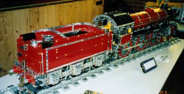
A magnificent locomotive by Mike Holland of Sydney Australia.
~
~
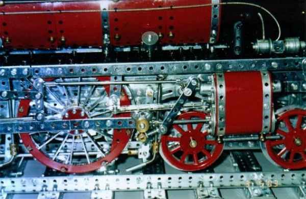
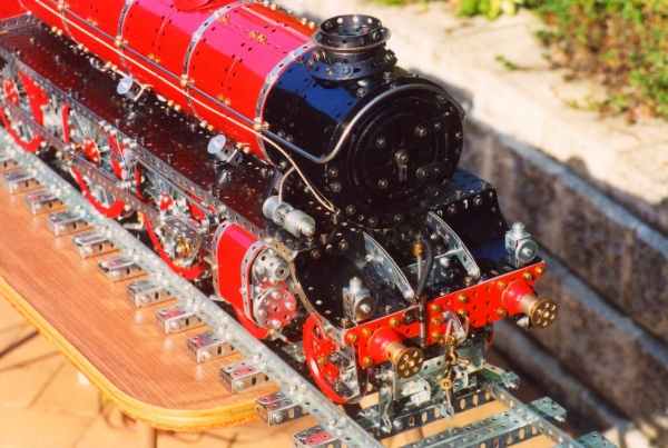
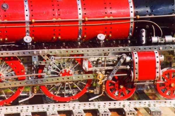
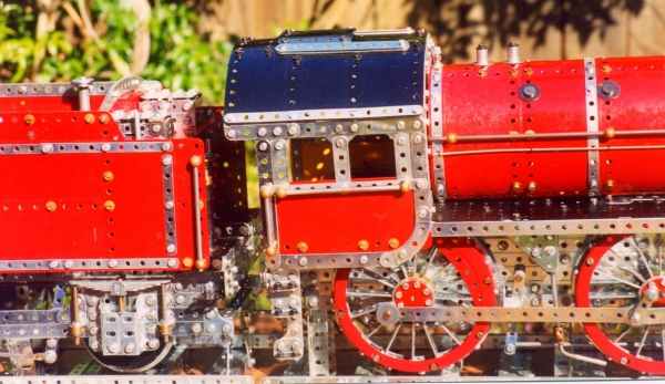
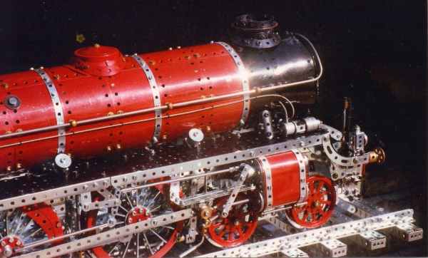
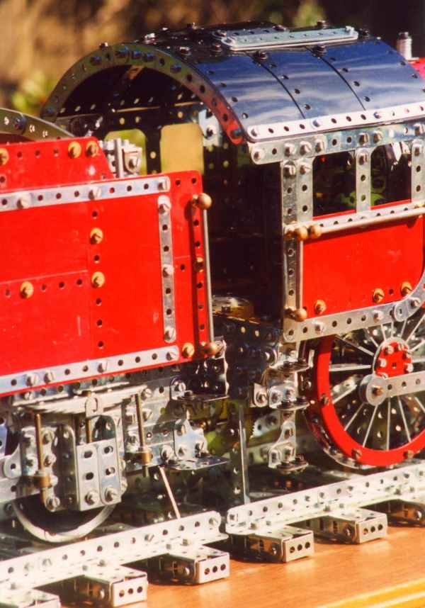
Above, detail of the wheels and valve gear and below five more close up images of the model, which incidentally is based on an LNER automotive .
~
~
~
~
~
Images supplied by Graham Jost, Melbourne, Australia gsjost@melbpc.org.au from spanner.
This model shows one way that Meccano can be utilized to build models. Another approach is to use the smallest possible scale as can be seen in these webpages on Meccano/Hornby crossover.
MECCANO CLASS B1 LNER LOCOMOTIVE
Text
supplied by Mike Holland
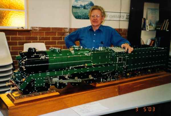
OK, so it is red! LNER locomotives should be green (or black). John Thomson of the Meccano Modellers Association (Sydney) has built a beautiful loco model using plates which he sprayed green - shown below:
But I am more interested in building than
restoring or painting parts, so I went ahead with what I had. It could have been
yellow, but I like red locomotives. Also, to do it in green one would have to
first build the model to determine what parts are required, then pull it apart
to spray them, and finally build it all over again. Insanity! John was restoring
an old model – not the same thing.
So why this
choice of locomotive ? Well, firstly I wanted a 4-6-0 wheel configuration; then
I wanted outside motion; and finally, I have always had a dislike for tapered
boilers (apologies to all you GWR fans out there). So I looked at LNER locos
with their parallel boilers, and chose the B1. I have a useful book, “Historic
Locomotive Drawings in 4mm Scale” by F.J.Roche, which provided all the views
and dimensions, and with a few photographs in other books, I was all set.
I will start with the construction of the wheels, as they set the scale of the model. For the drivers I used circular girders 143, and for the bogie spoked wheels 19a. The flanges for the spoked wheels were made from four curved stepped strips 90a. The problem here was to get the flanges close enough to the wheels, so I chose keyway bolts 231 for their small heads. The flanges are attached to the wheel using rod-and-strip connectors mounted on threaded pins which were screwed into the boss of the spoked wheel, the whole arrangement being nearly invisible from the front.
The flanges of the drivers were made up from 8 curved strips 90, bolted to the circular girder with long bolts and suitable spacers. As the circular girder is a little less than 5˝” in diameter, the curved strips protrude to form the flange. The 16 spokes each consist of two 2˝” strips attached to the rim of the girder by a ˝”x ˝” angle bracket - a total of 196 strips for the 6 wheels. Even with 2 strips, the spokes were a little thin, and could have been fattened up with 2” strips added on the outside. Once one has bent the brackets slightly to make the spokes point into the centre, by pure serendipity one finds that the strips leave a hole in the centre just right for a Meccano axle to pass through. The spokes are then clamped together in the centre between an 8-hole bush wheel and an 8-hole wheel disc using long bolts - two spokes between each pair of bolts. The wheel counter-weights are curved strips wedged between the spokes and the circular girder face.
The problem with this method of construction, of course, is that you have a wheel with bolt-heads all around the rim - not conducive to a smooth ride. Only suitable for a stationary loco raised off the track, with its wheels turning in the air. Could I have done better? Well, I put a lot of thought into this, and worked out a possible method. Instead of bolting angle brackets to the rim of the circular girder, bolt them to the curved strips at the back. But these would have to be narrow brackets to fit inside the circular girder, and bent at a slight angle instead of straight across to give clearance for the ends of the strips. So one takes 96 1” narrow strips and proceeds to bend them at the required angle. No doubt the result would be excellent, but hardly worth the effort!
Right. So we have a set of wheels. Next come the loco frames, and here I made the mistake of building them to scale, resulting in problems with the spacing of the wheels and motion. The wheels cannot be mounted as close to the frames as they should be, because of bolt heads all over the place. The motion rods could not pass each other and the surface of the wheels for the same reason. So I had to move bolts in the frames to prevent bolt heads colliding as the wheels turned, and then carefully choose the location of bolts in the coupling rods (˝” strips) to get everything to operate with as little clearance as possible. The alternatives were to rebuild the frames slightly narrower, or to have the cylinders about 1” out beyond the scale position. Some compromises had to be made.
Construction of the bodywork was all standard Meccano practice - you take two parts, a nut, a bolt, and a couple of washers ... No need to go into any detail here. The only items of interest would be the chimney and the steam dome. The dome was a boiler end with a conical disk on top. The mounting flanges around the base of it were made by putting an additional curve onto some curved strips. But none of the holes aligned with each other for fitting these strips, so I tied them in place with string. At the top of the chimney I placed a faceplate painted black with a silver rim, and on top of this a ring made from two curved black narrow strips. This ring could not be attached using angle brackets, as they would have ruined the appearance, so once again I used string. The whole boiler was located on 4 threaded pins, and could be lifted off to give access to the gears and motor.
A chain drive connected the axle of the front drivers with the axles of the bogie, so that the bogie wheels turned along with the drivers. Another drive, using contrates and universal couplings, connected the rear driving axle with the tender axles, which in turn were connected by chain drive, so that the tender wheels also turned. Gear ratios were chosen so that the smaller wheels turned twice as fast as the drivers.
In general, I am a Meccano purist, as this gives me the greatest challenge in my modelling. I do use replica parts, and I do paint parts to suit a particular model. This locomotive model is pure Meccano but for the handrail which curves around the front of the loco, for which I used a long piece of 4mm rod. Sadly, the model has already been stripped down due to lack of space, and the need for parts for the next model (probably a Showman’s Road Locomotive).